|
|

|
|
Front Axle RebuildBy Sifu-Lux - Click here to follow the topic WARNING: This article contains 120 photographs and will take long to load. I have now decided that I need to overhaul the front axle as it has been dripping oil for a while. That is a lot of work, so I will make it worth my labour and go all out :mrgreen: So, planned are the following to be done over the next month: 1 Remove the front axle and completely strip it and rebuild it.
Diff is OK so no need to remove. DONE As a start I am gathering all the bits and pieces I will need.
Have cleaned my spare front propshaft ready to go to the propshaft guys once I know how much longer it will have to be.
Took my spare torque rod and cut it in half. Removed 40mm and then threaded it with left and right thread. Threaded a matching piece of hex bar and had everything silver cadmium plated to stop corrosion.
Made up a set of 50mm x 50mm OD aluminium body spacers in case I need them, or feel the need to lift the body anyway :D . Had them anodised black to stop them corroding.
I have ordered all the axle seal kits etc from Toyota on Monday, so should get them tomorrow. Worked out to about R 2050 with the 15% discount I haggled for. I don't really have the time or want to source pirate kits from elsewhere for about a R400 saving overall. I only want to do the axle once. Ordered a set of Kumho KL71 MT's (R2020 ea fitted) and will have them fitted to once I have painted the rims which are currently in being beadblasted and primed. Will spray them at home with Acryline 2K black. Got the parts from Toyota that I ordered today for the axle overhaul
Today I started stripping the front axle out and finished this afternoon. About 5 hours work on your own.
Got some scrap racking today and modified it to make an axle stand to make it easy to work on the axle. Fits perfectly :)
Checked the spring perches quickly and you can see how warped they are. Will have to "Louis" them.
Cut the draglink today and shortened it by 35mm. Rewelded and machined, ready to go.
Today I started to strip the front axle. Here is the front hub before starting dis-assembly
First I removed the brake disk caliper (two bolts at the rear inner side)
Then I removed the bolts holding the free wheel locking hub dial in place and removed the dial. Locate the C shaped snap ring on the end of the sideshaft and remove it.
Then I removed the nuts and washers from the locking hub body. This leaves you with the cone washers which you then need to remove. After reading the many methods on offer via the internet to remove the cone washers, the method I found worked best was to spray them with penetrating oil, then using a brass drift and a hammer to hit the studs with a sharp smack one at a time. Going in a circular pattern from one stud to another. After about 5 to 10 smacks per stud, the cone washers started popping loose and could then be slid off the studs. Now you slide the hub body off.
Now remove the front bearing lock nut using your geyser spanner, then bend up the locking washer tabs, remove it, and then undo the bearing adjusting lock nut. Now you grab the disk brake rotor with both hands and slide it off the stub spindle. Be prepared to catch all the oil and grease mixture that may pour out if your axle has leaked as badly as mine. I had nice smelly bearing grease and diff oil mix
With the disk off, you see this
Now I removed the knuckle spindle mounting bolts and the dust seal and brake disk dust cover
Using a brass drift, I then tapped the knuckle spindle off the steering knuckle
Once this is off you can then remove the complete
birfield joint and sideshaft. Position one flat part of the outer
shaft upward and pull out the birfield joint and sideshaft. Again,
be ready to catch any leaking grease and oil slop.
Once this is out, then remove the top 4 nuts that hold the swivel bearing cap in place. This also has 4 cone washers. Tap out the bearing cap from the steering swivel hub housing.
Now remove the bottom bearing cap nuts, bearing cap and shims. Keep the specific shims together with the same bearing cap and bearings.
Undo the small bolts on the back of the swivel hub housing and remove the metal support plates, felt and rubber gaskets. Now you can remove the swivel hub from the axle. This is one really messy, dirty, crappy job
Here is the axle end with everything removed and wiped clean
With all that messy work done, I did the other side. Still being a sucker for more punishment, I stripped and cleaned the freewheel hubs
and cleaned and laid out the wheel bearings which I will be replacing
For info, the original wheel bearings are as follows:
Koyo Hi-Cap Front inner wheel bearing: JLM 104948-N Front outer wheel bearing: LM 102949 Swivel hub bearings are: Koyo TR 0305A (did not remove the bearing outer race, so can't see the part number) All bearings and races looked in excellent condition after 238 000 km. Not a mark I wanted to separate the brake disks from the hub to fit the new disks, but after removing the two retaining bolts I see that you also have to press out the wheel nut studs as these also hold the disk to the hub. Will have to get hold of a press, as I couldn't tap them out with a brass drift and hammer :( I would hate to know what Toyota would charge you just to replace your disks :shock: . After looking at the new disks and seeing that the minimum thickness stamped on them reads 11.4mm, I checked my disks and was shocked. One was 7mm thick, and the other 9mm. The previous owners must have skimmed them on the vehicle well beyond the allowable minimum thickness.
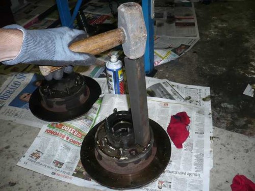
Gave the wheel studs a good spray last night and again this morning with penetrating oil. After reading all the potential stud removal methods on the internet, it seems that the common concensus is to hit them out with a hammer So I decided to "carefully" try again. Placed a spare wheel nut on the stud like so
then whack it like so with a piece of square bar and a hammer
About 5 very firm whacks per stud did the trick. Once you've got one out, you feel a bit better about the technique. With the studs removed (and the two retaining bolts) I tapped the bearing hub from the brake disk.
I needed to properly clean the axle outside in the garden, but it is too heavy for one person to carry, so I removed the diff pumpkin (good to check for dirt in the axle too) to lighten the load.
With that out I checked the inside of the axle. Very clean indeed, with no dirt visible. With the diff pumpkin removed, the axle can easily be carried around. I estimate is weighs around 25kg.
With the axle moved outside for cleaning, I carried on washing all the small parts with engine cleaner. A real "#%!!!!" job.
Some 4 hours later and .... (and no, I didn't wash them in the pool)
OK, so last update before I go to bed Hope Pietpetoors doesn't need to buy a new server for all the pics Decided to end the evening off by fitting the new brake disks. SWAMBO said I should consider putting my bed in the garage I cleaned up the hub/disk mating faces with a wire brush on my electric drill, then painted the exposed metal casting pieces with rust converter.
Applied a layer of Copperslip/Neverseize copper compound to the
mating face
Then fitted the disk to the hub with the two retaining bolts. I will fit the wheel studs later.
I then took the time to inspect the recently cleaned brake calipers. Will definitely have to strip them and put in a new seal kit as the dust seals are shot.
The last job tonight was to wash out and soak the Birfield / CV joints in paraffin. Will strip them next week and check the condition.
I spent last night cleaning, prepping and spraying some parts. Tonight I tackled the Birfield CV joints. The sideshaft fits into the inner race of the Birfield joint and is held in place by two snap rings. The outer one you can see, but the inner one is inside the joint. This one has to be broken :shock: to get the sideshaft out of the joint. I tried the brass drift with hammer method from the manual, but got nowhere fast. Method two, which worked, I got from a website somewhere. Place a piece of pipe in the vice. The inner diameter of the pipe should be just bigger than the sideshaft outer diameter. Now, take the Birfield joint and sideshaft assembly and place the sideshaft in the pipe. Lift it up in the air as high as you can, then let it go. The sideshaft drops into the pipe, but the Birfield inner race is too big to go in, and therefore stops suddenly. This shock breaks the inner snap ring (see photo below) and the sideshaft comes out. This took several attempts, but worked. Below is the sideshaft separated from the Birfield CV joint, with the broken inner snap ring shown. Shaft inner snap ring: 43411B 90520-28036
Wih the sideshaft out, you can now remove the balls and the inner and outer races.
Here is the whole assembly in pieces, after some initial cleaning. Off to the dealer tomorrow to get new snaprings
Andy Asked: Andrew Answer: Got my new snap rings today from Toyota. R 16 ea. Spent some time this evening re-assembling the locking hubs. I must say, stripping them was a good way to learn how they work, and they are not that complicated to re-assemble (provided you have a good manual) Tomorrow I will try to panel beat the spring perches/saddles back to factory spec :mrgreen: Just got to figure out the best way to do it. Today was caliper overhaul day :eh: On closer inspection of the front brake calipers I found that
the one caliper was missing all the piston dust seals and the
dust seals on the other caliper were totally torn and trashed. First I stripped the calipers. I used compressed air as per the manual to get the first piston out. It came out with a pop and I ended up covered in brake fluid. This method is not really advisable as it is difficult to control, and once one piston is out, you cannot really seal the cylinder bore to allow the use of compressed air on the others. I ended up using a pair of waterpump pliers on the front lip and twisting them out carefully. Took a while. The pistons and were in quite good condition, with only minimal rust pitting in some places near to top of the piston body. Poilished all the pistons up with 1200 grit waterpaper and washed them. Then painted rust converter on the rusty bits exposed to the outside of the caliper.
The internal cylinder bores were in perfect condition.
After cleaning everything, I fitted the new seal kit. Coated everything with Red Rubber Grease. Assembly was a lot quicker than stripping.
I then degreased the calipers and painted them black with etch primer /Jetmaster black paint and fitted the new Ferodo pads. All done!
Still having a bit of energy, I reassembled the freewheel locking hubs. I needed the help of SWAMBO to get the one snap ring back that hold the freewheel hub body to the inner hub. She was not impressed having to hold "dirty greasy" things as she called them. I don't know what she was on about, they were sparkly clean with new, fresh LM grease
Put the cover and dial on to the body and checked them for correct engaging and dis-engaging. All OK!
Now I need to start the spring perch/saddle correction work. I have looked at this from all angles, and cannot come up with the best method to re-shape the saddles. I put the axle in the vice earlier, and then gave the saddles a few whacks with my square bar and hammer, but nothing moved. Tried "squashing" the saddle sides upright again in the vice, but no joy. Will have to think about this some more. So I went and read Louis's post ( front axle saddle correction ) again. I had it backwards :wth: . With Louis's method, you need to hammer the middle high point down, not the bent lower ends up (which made logical sence to me as they are the parts that bend?). Anyway I'll go off now and hammer the Cr@p out of the saddles Found an acceptable way of holding the axle in the vice and supporting the saddle on a piece of steel. Marked the high points and then smacked them down with my big hammer
When you beat the saddles flat with the hammer you can get the middle, unsupported area flat quite easily. The sides however need to have the high points massaged with an angle grinder, then dressed with a fine metal file to get the sides flat.
Once that was done I gave the axle a quick sand
with a flapper wheel in the drill to remove any loose paint and
surface rust, then painted the axle with rust converter. I then
marked out the position of the new holes I needed to drill to
allow for the axle to be moved 35mm forward.
Gave the whole axle a quick coat of black etch primer to neaten it up.
Using the sheet of Flexoid gasket paper, I used the other gasket (Toyota was out of stock of this one and couldn't supply for a month) as a template, and cut it out with a razor blade knife. Fitted it to the spindle and trimmed to the correct shape. Then I used a hole punch and a block of wood to punch the required 10mm holes.
Here are the two completed gaskets.
I made a quick drawing of the tool I want to make to use when fitting the sideshaft oil seals to the axle. It is reasonably difficult to ensure that the oil seals are driven in squarely as you have to work inside the ball end of the axle, so this tool will make it easier. Will get the tool made tomorrow.
Last night I re-inforced the spring saddles with steel flat bar. For my needs, the sizes required were as follows: 112 x 40 x 10mm Steel flat bar (2 pieces)
I then welded in the flat bars as below pics, then painted everything with black etch primer.
**EDIT today on fitting day. I screwed up here. I made the re-inforcement flat bar wider than the spring saddle. Definitely not thinking. Had to cut the extra width off with an angle grinder so the U-Bolts could be fitted. I suppose I am allowed one mistake Once the saddle re-inforcements were done, I turned to replacing the studs in the axle that hold the diff pumpkin in place. The old ones were rusted and some nuts were seized on. I first cleaned the gasket mating face, then installed the new studs, using Loctite retaining compound.
With the studs replaced, I put the diff pumpkin in the vice, and cleaned the gasket mating face. On close inspection of the diff, I found the one bearing retaining bolt head and a part of the backlash adjuster were rusted, so I had to clean them up. This is why it is important to engage the front locking hubs at least once a month and go for a drive to allow the diff to turn in the diff oil and keep it coated in oil (Which I obviously didn't do often enough )
I then had to make a gasket out of Loctite Ultra Grey silicone, as the paper gasket I bought from Toyota did not fit The diff was then installed with new washers, spring washers
and nuts, using Loctite thread locker.
I got my oil seal inserting tool made today
The new oil seal fits nice and snuggly on the tool, ready for insertion.
Here is the tool being used to install the oil seal nice and squarely in place. You don't need a tool like this, but it made the job super easy.
Here is the tool being used to install the oil seal
nice and squarely in place. You don't need a tool like this, but
it made the job super easy. I coated the oil seal inner face with red rubber grease. Next job was to install the swivel hub bearing races.
I cleaned the recesses and then put on Loctite medium strength thread
locker to make sure they stay in place.
I then placed the new swivel hub rear oil seal kit over the axle ball end. It goes on in the order of felt ring, then rubber ring, then steel ring.
Last job for tonight was to put the new wheel bearings into the hubs. I used the old bearing race to drive the new inner wheel bearing race into the hub. Worked great.
I then filled the hub cavity between the inner and outer bearings with Castrol WB grease, and greased the inner wheel bearing and installed it.
The inner wheel bearing oil seal was then installed. Again I used the old wheel bearing race as a tool to evenly drive in the new seal.
I then turned the hub over and installed the outer wheel bearing and race.
Have just been accused of being anti-social by SWAMBO,
so had better go pay some attention So, Wednesday night I started to assemble the swivel hubs. First I cleaned up all the gasket faces so they were clean and shiny. Then I greased to swivel hub bearings with Castrol MS grease and installed them on the axle.
I then placed the swivel hub in position and pressed
the top and bottom bearing caps with their respective shims into
place. Put copper grease on the cone washers (split dowels) and
tightened the nuts up.
With that done I re-assembled the Birfield / CV joint race cages and balls and greased them up with MS grease. To install the sideshaft into the cage you need to place the Birfiled joint in the vice, then place the sideshaft end into the inner race until it contacts the first thin metal snap ring. You then need to compress the first snap ring (shown below) and tap the sideshaft into the inner race. Believe me, for this you need two people. Luckily for me, my dad happened to ring my doorbell at this point. Unlucky for him, he was about to get dirty
With the Birfield joints and sideshafts assembled, I greased the axle oil seals and sideshaft inner ends with a generous layer of Red Rubber grease, then slid the assembly into the axle tube. Remember the Birfiled joint housing "flats" must be at the top and bottom to get the joint into the axle properly.
Now came the messy part ! Packing the swivel hub housing
with MS grease. Pack with grease to 75% of the volume of the swivel
hub.
I lot of cleaning followed (mainly of myself ). I then fitted the gasket I made earlier to the axle spindle shaft which bolts to the swivel hub. I used a bit of gasket shellac on the paper gasket.
I then placed the spindle onto the hub and tapped it into position with a nylon hammer.
Next to go on is the brake disk dust shield. As this is fitted to the spindle face without a gasket, I put a thin coating of copper grease on the mating faces.
The paper gasket and dust seal go on next. Once these are on, the whole assembly can be bolted together.
Be careful not to let the driveshaft stub push the outer wheel bearing out when you slide the assembly on. Besides dropping the bearing on the floor in the muck, it may land on your toes
Now you can insert the thrust washer, followed by
the wheel bearing adjusting nut. Here a geyser element spanner works
well to tighten the nut. First tighten it quite tight, then turn
the hub in the forward direction to make sure the bearings have
seated properly. Now you loosen it a bit and then use a fish scale
to measure the seal drag, the retighten and set the bearing preload
as per the workshop manual.
As the bearing preload is now set, you fit the locking tab washer, the the wheel bearing lock nut and tighten it. Re-check the bearing preload with the fish scale, then bend over the tabs on the lock washer. After cleaning the mating faces, fit the freewheel hub body gasket, and fit the freewheel hub. I put copper grease on the cone washers again and then tightened everything up.
In the photo above, you see a bolt sticking out of the driveshaft end. I used this to pull the driveshaft out a bit so the snap ring groove is exposed. The shaft stub snap ring is now fitted.
Next to go on is the freewheel hub dial face and gasket. I coated all the sliding parts with a bit of MS grease then assembled the dial to the hub body. I replaced all the old mounting bolts which were a bit damaged and worn with stainless steel Allen cap bolts and stainless washers.
Today I got home at 16h15 and went straight to the garage, eager to finish this axle after two weeks of work. It looks like this overhaul job took about 60 hours of labour to do it properly :shock: Anyway, all I had to fit were the brake calipers, and give the axle a quick touch up with some black etch paint. Here are the calipers fitted with the new pads, and the anti rattle springs which I found on my spare front axle.
And ....... ALL DONE !!!
I fitted the wheels, and lowered the axle down to
the floor, ready for installation tomorrow afternoon.
This was a big job. Not that difficult at all, but time consuming. I learnt a lot about the working and assembly of the front axle though. Quite a bit of fun, but I won't do it in a hurry again, or for anybody else Here are the costs so far for the axle overhaul portion of the project. I've included all the part numbers I could of the spares you need. Click here to download the costs spread sheet Did not get much done until we got home after lunch. I cleaned up the U-Bolts and axle / spring clamps and then marked out and re-drilled the holes in the bumpstops. The holes must be moved 35mm back to allow for the nut of the bolt that holeds the leaf spring pack together. Here is the bumpstop mounted with the leafspring pack nut showing through the new relocated hole.
My mate arrived later and so I roped him into helping me fit
the front axle in position.
Once it was in and lined up, I fastened the U-Bolts then lowered
the Lux onto its wheels and removed the tressels it was supported
on. Did a final position check then tightened everything up.
With all that done, I was itching to see what the new 33" MT's would look like, so I fitted one Looks pretty darn good
This morning I started to reconnect all the bits and pieces to the axle. I started by re-installing the shocks to their lower mounting
points on the axle. Because the axle is now 35mm further forward,
I needed to bend the lower mounting brackets at a slight angle
to accomodate the new angle of the shocks.
Next I refitted the shortened drag link. Went on OK, but I need to check the clearance between it and the rear U-Bolt to make sure it is still OK after the mod, as it will now run at a slightly steeper angle.
I then moved on to reconnecting the brake lines, and I then bled the entire system and flushed it out with new brake fluid to all the wheels and the load proportioning valve. While I was at it I also replaced the clutch fluid and bled it too.
I also re-filled the front diff with new oil (Castrol EPX 80W90 GL-5) and then drained and refilled the rear diff too. Then for the moment of truth. Would my home designed adjustable torque rod work ? Well, it fitted first time :thumbup: Made some small adjustments to the length and then tightened the bolts and fasted the lock nuts.
With all that done, I fitted the rest of the wheels with the remaining 33" tyres, and here's the result.
I then temporarily installed the front propshaft so I could measure the exact length I need to lengthen it. It worked out that I need to make it 45mm longer. 35mm for the axle move + 10mm for the extra height from the OME springs. With all that done, I called it a day. Some time next week I will take the propshaft in to have it done. So, almost there ! I will drive the Lux a bit first, before I see wether the body lift will be necessary, but from what I can see, the front edge of the front tyres are possibly going to snag on the rear of the front bumper plastic corner during maximum articulation. I went and had the propshaft made longer by 45mm today. They cut the old tube off and then welded in a new longer tube, balanced it, greased it and painted it. All in one and a half hours, and only R 250 :D At this point, I must say I can really recommend Vasco at PE Propshafts. Really customer oriented and fussy about a quality job. I even got a cup of tea while I waited (and watched what they were doing in the workshop :mrgreen: ) Here is the modified propshaft being balanced
Here is the modified front propshaft next to the original one
Since it looked a bit bare, I found a place for my left over forum sticker
I then cleaned up all the flange mating faces, wiped them with a small amount of copper grease and fitted the front propshaft, and here's the result
I took the Lux for a quick spin around the neighbourhood
to check everything still works :think:
Anyway, here is the long awaited final result
|
| For info, the original wheel bearings
are as follows: Koyo Hi-Cap Front inner wheel bearing: JLM 104948-N Front outer wheel bearing: LM 102949 Swivel hub bearings are: Koyo TR 0305A (did not remove the bearing outer race, so can't see the part number) Shaft inner snap ring: 43411B 90520-28036 Front disc rotors – Motopart MSD4277 |