|
Some points
to consider when you install a dual battery system:
1. Get an “El
Cheapo” digital multimeter (DMM) from Midas, P&P etc (R
50.00).
2. Make sure of point 1, and learn what’s amps, volts, ohms!
3. Use at least 25 square mm cable (6 mm diameter), Builders Warehouse
or Midas @ about R50 / m, but it’s worth it. This is the copper
I’m talking about, not the copper and the insulation, dummy!
4. Get the right size lugs, and solder them after crimping! If you
don’t have a big enough soldering iron, maybe it will work
to heat them over a gas flame!
5. Depending on your specific vehicles’ configuration, connect
the positive cable DIRECTLY to the positive terminal of the alternator.
The idea is to minimise IR drop. Check the diagram.

6. Connect the
negative cable DIRECTLY to the engine, again to minimise IR drop.
7. Install 2 x 63 Amp circuit breakers, one as close as possible
to the alternator, one as close as possible to the aux battery.
The danger is that the cable will chafe through and short circuit
through to the chassis. As a battery can easily supply more than
200 Ampere, that cable will be red hot very quickly, a breaker @
R 50 is cheap compared to a vehicle!
8. Use high quality connectors (Brad Harrison or Anderson) for any
connect/disconnect points to the fridge, aux battery etc. Outdoor
Warehouse, Makro stock them.
9. Use a simple control diagram that you understand. I activate
a normally open toggle switch (or push button), which activates
2 relays, which activates a Cole Hersee Constant rated solenoid.
You can use a marine solenoid as well. Look at the circuit diagram
for details. I must activate the circuit manually, but it switches
off as soon as I switch off the ignition. Don’t want to drain
both batteries. On www.overland.co.za there’s web addresses
and battery theory and circuits and enough info to satisfy everybody!
PB switch mean that the switch is activated when you push it, but
returns to the open position when you release it, so it doesn’t
stay switched!

10. Buy and install a shunt resistor. This will enable you to know
what the charging current to your aux battery is. Even better, buy
2 and install one in the main battery line as well, then you know
all charging currents. The shunt will give a certain millivolt for
a certain current, if your DMM is switched to the 200 mV scale you
can read the amps.
11. Tie everything securely with cable ties.
This is what
the shunt looks like, note the isolators.

And this is
the circuit diagram to measure current.

12. I also use a dual battery monitor from National Luna (R 300).
Quite handy, because it gives you immediate feedback if your circuit
is working.
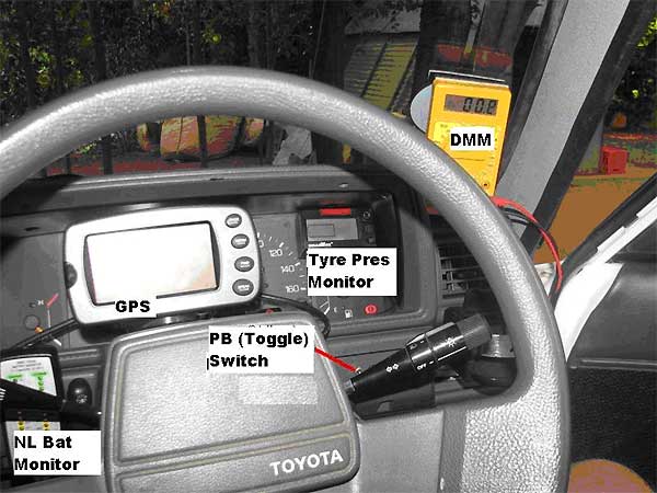
Here’s
a few photos of my set-up.
Yellow cheap
DMM on the right-hand side (for charge current indication), tyre
pressure monitor, GPS and dual battery monitor.
The toggle switch to activate the charge circuit you can see behind
the light stalk.
This is the shunt and 63 Amp breaker installed.
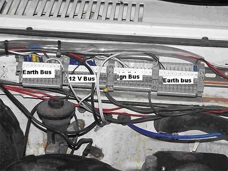
I also installed
terminals and breakers to supply all the various auxiliary gadgets.
One can buy industrial type terminals, which is bridged in groups
of 10. I have 4 of those, 2 for negative terminals, 1 for permanent
12 volt and 1 for ignition 12 volt (only power when you switch on,
e.g. tyre monitor). Let’s call this terminal strip a “bus”,
e.g. 12 v bus, ign bus and earth bus.
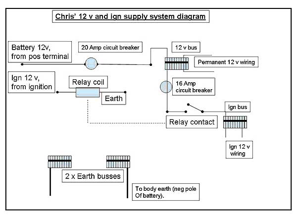
For the 12 volt
bus I took a thickish wire through a 20 A breaker from the battery,
then to the 12 volt bus.
For the ignition
bus I opened the ignition cover, and found the contact which is
powered when you turn the key to ignition (not start). Use the gadget
in (1) for this. I soldered a wire on the contact and threaded it
through the firewall to a relay which is then activated when I turn
the key. From the permanent 12 v bus I connected a wire to the one
side of the contact, then through a 16 A breaker to the ign bus.
Now I have enough
connection points for all the gadgets, and they are protected by
breakers.
This is the circuit:
This is a picture
of the 63 Amp breaker for the aux battery, the 20 Amp breaker for
the 12 volt bus, and the 16 Amp breaker for the ignition bus.

The breakers
and terminals are installed on what is known as slotted DIN rail,
available from electrical suppliers. There’s enough 6 mm threaded
holes in the firewall to install the DIN rails, the breakers and
terminals clip onto them, no need to drill holes.
Here is a photo
of the terminals (buses), I must still tidy up.
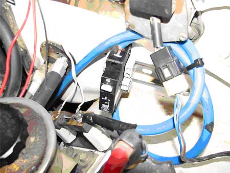
Here’s
a photo of all the relays.

ENJOY
YOUR DIY INSTALLATION!!
|
