In
this article, I will discuss the 2 main types of axles in use in 4x4
vehicles today namely solid axles and independent axles. There are also
a third type in use called portal axles but this configuration is used
seldom, normally only in off-road trucks like the Mercedes Unimog
truck, but I will not discuss them as they are not really relevant to
the target audience of this article.
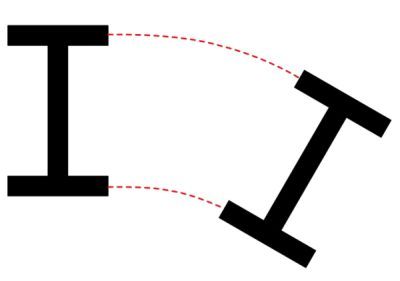
In all vehicles, the
driving wheels are attached to axles that facilitate power delivery to
the wheels. Most vehicles’ axles contain a differential in the centre
of the axle to allow the differences in rotational speeds between the
left and right wheels to be absorbed or cancelled out. This difference
in speeds occur when the vehicle does not move in a straight line and
the wheel inside the turn move slower due to a shorter path travelled
compared to the outer wheel that travels a longer path.
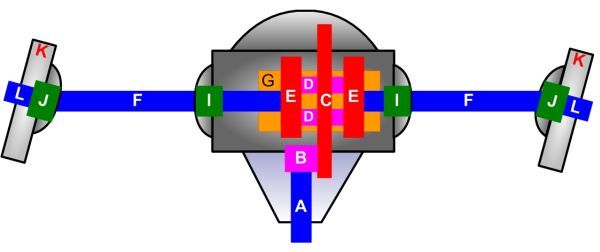
The Differential is the centre portion of the axle and contains the following components:
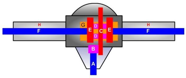
The casing that holds all the pieces intact is called the diff carrier (G)
On
imported differentials the triangular piece at the bottom of the
picture including the diff mechanism (carrier, gears, pinion and
bearings) can screw loose separately and this is called the 3rd-member.
The input shaft is called the pinion
(A) and the gear at the end is called the pinion gear
(B)The
rotation from the prop shaft that is connected to the pinion rotates
the pinion gear which in turn drives the ring gear or crown wheel
(C)Attached to the crown wheel is the spider gears or sometimes called planetary gears
(D) The
spider gears in turn drive the side gears and this is the heart of the
differential system. This setup will allow rotational speed differences
to be absorbed or cancelled out by the spider gears. If both wheels
rotate at the same speed, then the spider gears stand still and the
side gears and crown wheel turn in unison. A differential lock can be
installed into the carrier which will lock the side gears and crown
wheel together and will cause equal power transfer to both wheels, if
one of them were to loose traction.
Read the article on
http://auto.howstuffworks.com/differential.htm which explains differentials in more detail.
Check out these cool animations which show a differential while the vehicle is driving straight and when it is turning
http://static.howstuffworks.com/flash/differential.swfThe side gears drive the wheels via the side shafts. There are a few diff configurations in use.
The
first is a solid rear axle also called a rear beam axle and does not
have any rotational joints attached to the side shafts .
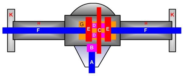
The
side shaft covers or beams (H), the centre portion, also referred to as
the pumpkin, and the wheel hubs (K) are one solid piece.
The next configuration is a solid front axle or front beam axle.
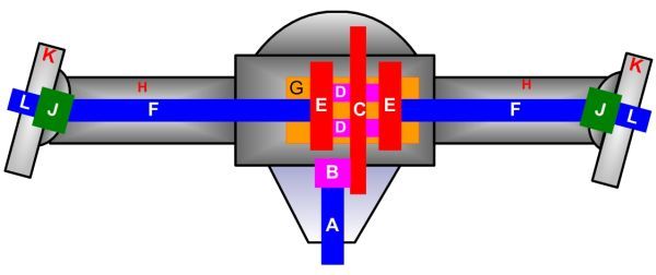
In
this case the beams and the pumpkin is still a solid unit but at the
ends there are swivel hubs that allows the steering wheels in front of
the vehicle to be turned left or right.
In order to facilitate this turning movement in the side shaft while it is rotating, rotational joints
(J)
are placed at the ends of the side shafts and connects the stub axles
to the side shafts. These joints can either be universal joints as used
in DANA axles, Birfield joints as used in the Toyota solid front axles
or constant velocity (CV) joints as used in most vehicles with
independent front or rear suspension
The next configuration is a independent rear axle
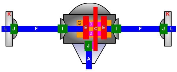
In
this configuration, the hubs and side shafts move independently from
the pumpkin that is fixed to the vehicle, so it remains stationary
while the wheels and side shafts move independently.
To be able
to achieve this, two rotational joints (normally CV joints) are placed
at the ends of the side shaft. The inner CV (I) connects the side shaft
to the diff and the Outer CV (J) connects the side shaft to the sub
axle.
In this configuration the side shafts are often exposed.
The next configuration is an independent front axle
The
independent front axle works just as the independent rear axle, except
that it also have swivel hubs at the ends like the solid front axle to
facilitate steering of the vehicle.